- 您现在的位置:买卖IC网 > Sheet目录1991 > CS4341-CZZ (Cirrus Logic Inc)IC DAC STER 24BIT 96KHZ 16TSSOP
CS4341
14
DS298F5
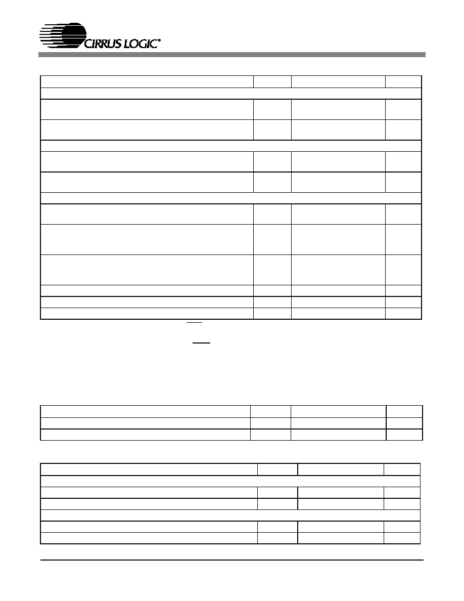
DC ELECTRICAL CHARACTERISTICS (AGND = 0 V; all voltages with respect to AGND.)
Notes: 13. Normal operation is defined as RST = HI with a 997 Hz, 0 dBFS input sampled at the highest Fs for
each speed mode, and open outputs, unless otherwise specified.
14. Power Down Mode is defined as RST = LO with all clocks and data lines held static.
15. Valid with the recommended capacitor values on FILT+ and VQ as shown in Figure 16. Increasing the
capacitance will also increase the PSRR.
DIGITAL INPUT CHARACTERISTICS (AGND = 0 V; all voltages with respect to AGND.)
DIGITAL INTERFACE SPECIFICATIONS (AGND = 0 V; all voltages with respect to AGND.)
Parameters
Symbol
Min
Typ
Max
Units
Normal Operation (Note 13)
Power Supply Current
VA = 5.0 V
VA = 3.0 V
IA
-
15
11
18
14
mA
Power Dissipation
VA = 5.0 V
VA = 3.0 V
-
75
33
90
42
mW
Power-down Mode (Note 14)
Power Supply Current
VA = 5.0 V
VA = 3.0 V
IA
-
60
30
-
A
Power Dissipation
VA = 5.0 V
VA = 3.0 V
-
0.3
0.09
-
mW
All Modes of Operation
Power Supply Rejection Ratio (Note 15)
1 kHz
60 Hz
PSRR
-
60
40
-
dB
VQ Nominal Voltage
Output Impedance
Maximum allowable DC current source/sink
-
0.45VA
250
0.01
-
V
k
mA
Filt+ Nominal Voltage
Output Impedance
Maximum allowable DC current source/sink
-
VA
250
0.01
-
V
k
mA
MUTEC Low-Level Output Voltage
-
0
-
V
MUTEC High-Level Output Voltage
-
VA
-
V
Maximum MUTEC Drive Current
-
3
-
mA
Parameters
Symbol
Min
Typ
Max
Units
Input Leakage Current
Iin
--
±10
A
Input Capacitance
-
8
-
pF
Parameters
Symbol
Min
Max
Units
3.3 V Logic (3.0 V to 3.6 V DC Supply)
High-Level Input Voltage
VIH
2.0
-
V
Low-Level Input Voltage
VIL
-0.8
V
5.0 V Logic (4.75 V to 5.25 V DC Supply)
High-Level Input Voltage
VIH
2.0
-
V
Low-Level Input Voltage
VIL
-0.8
V
发布紧急采购,3分钟左右您将得到回复。
相关PDF资料
CS4341A-KSZ
IC DAC STER 24BIT 192KHZ 16SOIC
CS4351-DZZ
IC DAC STER 112DB 192KHZ 20TSSOP
CS4352-DZZ
IC DAC STER 102DB 192KHZ 20TSSOP
CS4354-CSZ
IC DAC 24BIT SRL 14SOIC
CS4360-KZZ
IC DAC STER 6CH 102DB 28TSSOP
CS4361-CZZR
IC DAC STER 6CH 105DB 20-TSSOP
CS4362-KQZ
IC DAC 6CH 114DB 192KHZ 48LQFP
CS4362A-DQZ
IC DAC 6CH 114DB 192KHZ 48-LQFP
相关代理商/技术参数
CS4341-CZZR
功能描述:数模转换器- DAC IC 24bit 96kHz 101dB Stereo DAC w/VC RoHS:否 制造商:Texas Instruments 转换器数量:1 DAC 输出端数量:1 转换速率:2 MSPs 分辨率:16 bit 接口类型:QSPI, SPI, Serial (3-Wire, Microwire) 稳定时间:1 us 最大工作温度:+ 85 C 安装风格:SMD/SMT 封装 / 箱体:SOIC-14 封装:Tube
CS4341-KS
功能描述:数模转换器- DAC 24-bit 96kHz 101dB Stereo DAC w/VC
RoHS:否 制造商:Texas Instruments 转换器数量:1 DAC 输出端数量:1 转换速率:2 MSPs 分辨率:16 bit 接口类型:QSPI, SPI, Serial (3-Wire, Microwire) 稳定时间:1 us 最大工作温度:+ 85 C 安装风格:SMD/SMT 封装 / 箱体:SOIC-14 封装:Tube
CS4341-KSR
功能描述:数模转换器- DAC 24-bit 96kHz 101dB Stereo DAC w/VC
RoHS:否 制造商:Texas Instruments 转换器数量:1 DAC 输出端数量:1 转换速率:2 MSPs 分辨率:16 bit 接口类型:QSPI, SPI, Serial (3-Wire, Microwire) 稳定时间:1 us 最大工作温度:+ 85 C 安装风格:SMD/SMT 封装 / 箱体:SOIC-14 封装:Tube
CS4341-KSZ
制造商:Cirrus Logic 功能描述:24-BIT, 96 KHZ STEREO DAC WITH VOL CNTRL - Bulk 制造商:Cirrus Logic 功能描述:IC DAC 24BIT SRL 96KHZ 16-SOIC 制造商:Cirrus Logic 功能描述:24Bit 96kHz 101dB Stereo DAC
CS4341-KSZR
制造商:Cirrus Logic 功能描述:DAC DUAL DELTA-SIGMA 24BIT 16SOIC - Tape and Reel
CS4344
制造商:CIRRUS 制造商全称:Cirrus Logic 功能描述:10-PIN, 24-BIT, 192KHz STEREO D/A CONVERTER
CS4344_05
制造商:CIRRUS 制造商全称:Cirrus Logic 功能描述:10-PIN, 24-BIT, 192KHz STEREO D/A CONVERTER
CS4344-CZZ
功能描述:音频数/模转换器 IC Stereo DAC 24-Bit 192kHz RoHS:否 制造商:Texas Instruments 转换器数量: 分辨率:16 bit 接口类型:I2S, UBS 转换速率: 信噪比:98 dB 工作电源电压:5 V DAC 输出端数量:2 工作温度范围:- 25 C to + 85 C 电源电流:23 mA 安装风格:SMD/SMT 封装 / 箱体:TQFP-32 封装:Reel